vSphere With Tanzu - Enable Workload Management in vSphere 7 update 3
This post will take a look at the configuration steps needed in vCenter for deploying vSphere with Tanzu (TKGs) using NSX Advanced Load Balancer (Avi Vantage) as the load balancer.
The configuration of the Load Balancer can be found here
I will use the latest version available of Avi (22.1.1) in this post, please make sure you verify the compatibility between the Load balancer and the solution you'll use it for.
From the latest vSphere with Tanzu release notes the NSX Advanced Load Balancer version mentioned is 20.1.7. If you want official confirmation on the compatibility you should consider contacting VMware support
Prerequisites
There's a few prerequisites that needs to be met before setting up a Supervisor cluster besides a working vSphere 7 cluster:
HA and DRS needs to be enabled in the cluster, and the cluster should consist of minimum three hosts.
A working network stack based on either vSphere distributed switches or NSX-T. If not using NSX-T we will also need to bring a supported Load Balancer for the Supervisor cluster, either based on the NSX Advanced Load Balancer (which we will use in this setup) or HAProxy.
We need to have a Storage Policy configured which is used for determining the datastore placement of the resources deployed.
We will also need a Content Library for storing OVA templates for the different Tanzu Kubernetes releases. Note that the Content Library is not used for deploying the Supervisor control plane nodes and could as such be empty when enabling Workload Management.
Refer to the vSphere documentation for details and more information
Lab environment
In this post we'll work with a vSphere environment, based on vCenter and ESXi on the 7.0.3 (Update 3f) version.
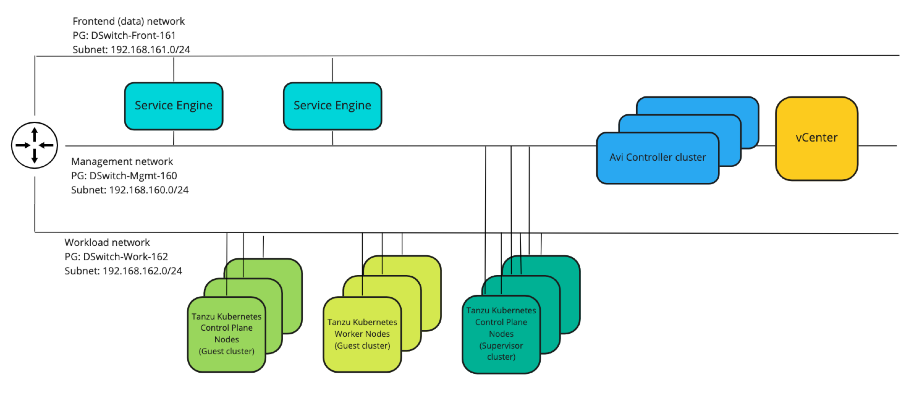
The networks in play here and where we'll see stuff being deployed are as follows:
| Subnet | VLAN | GW | Comment |
|---|---|---|---|
| 192.168.160.0/24 | 160 | 192.168.160.1 | Management network (vCenter, ESXi, Avi controller) |
| 192.168.161.0/24 | 161 | 192.168.161.1 | Frontend/load balancer network (Avi VIPs) |
| 192.168.162.0/24 | 162 | 192.168.162.1 | Workload network (Load balanced workloads/web servers) |
There's routing between these networks and also to the outside world. No firewall rules exists between these (that's for a later post).
A simple drawing of the network would be something like the following
There's also DHCP services available in all of the networks with a scope in each network with the IP range 192.168.16x.100-192.168.16x.199
There's one exception with regards to the networks in use, and that concerns my DNS server which is served from a different network. The three networks mentioned above have access to the DNS services on this server
There's three ESXi hosts running in the cluster we will use, and the storage is based on vSAN. Note that any supported shared vSphere storage works.
We have a Storage Policy created called tkgs and an (empty) Content Library also called tkgs.
Licensing
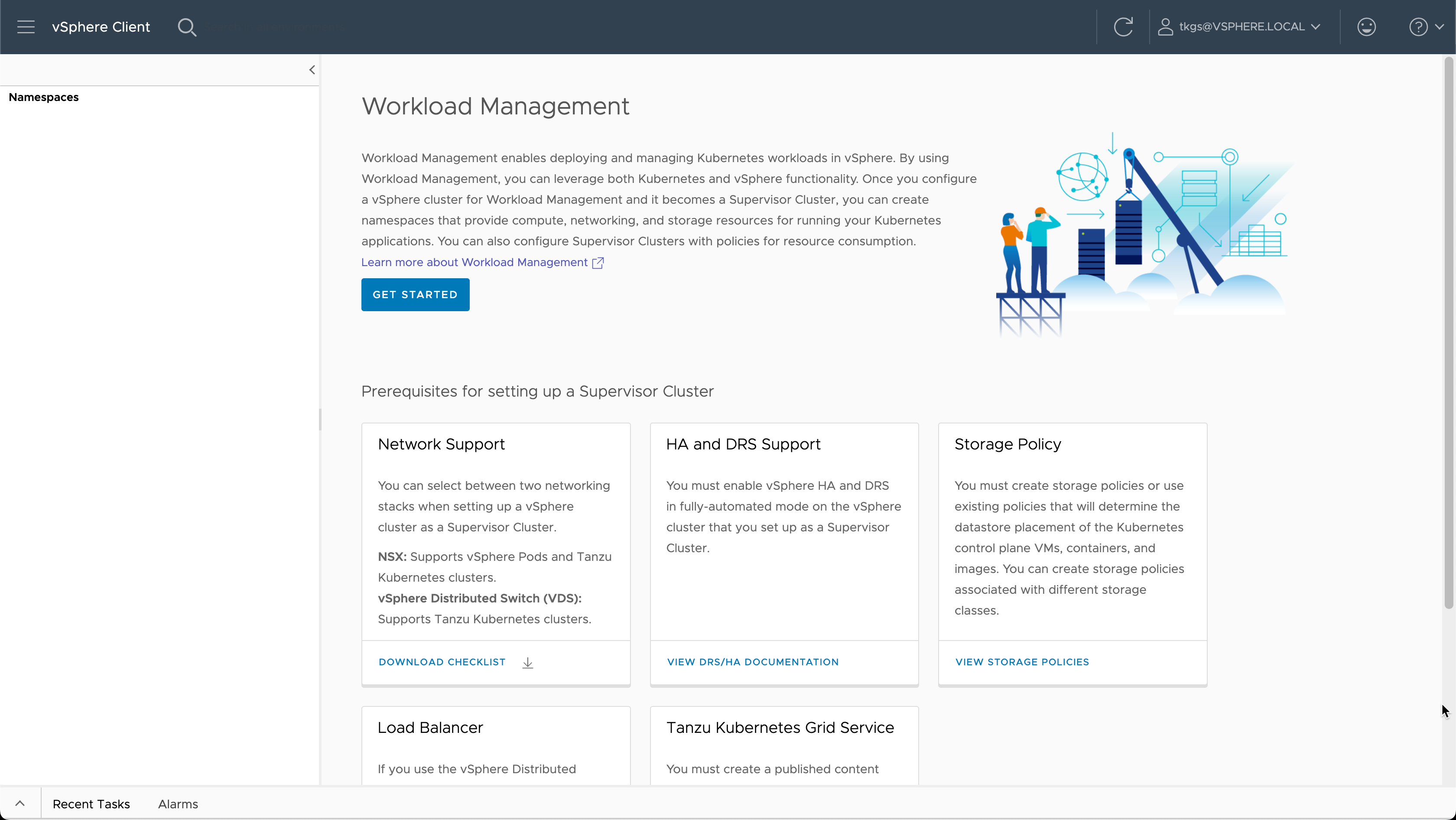
Before configuring Workload Management we would either add a valid license for Tanzu, or fill out the evaluation form found in the Workload Management section.
In my environment I've added a Tanzu Basic license.
Enable Workload Management
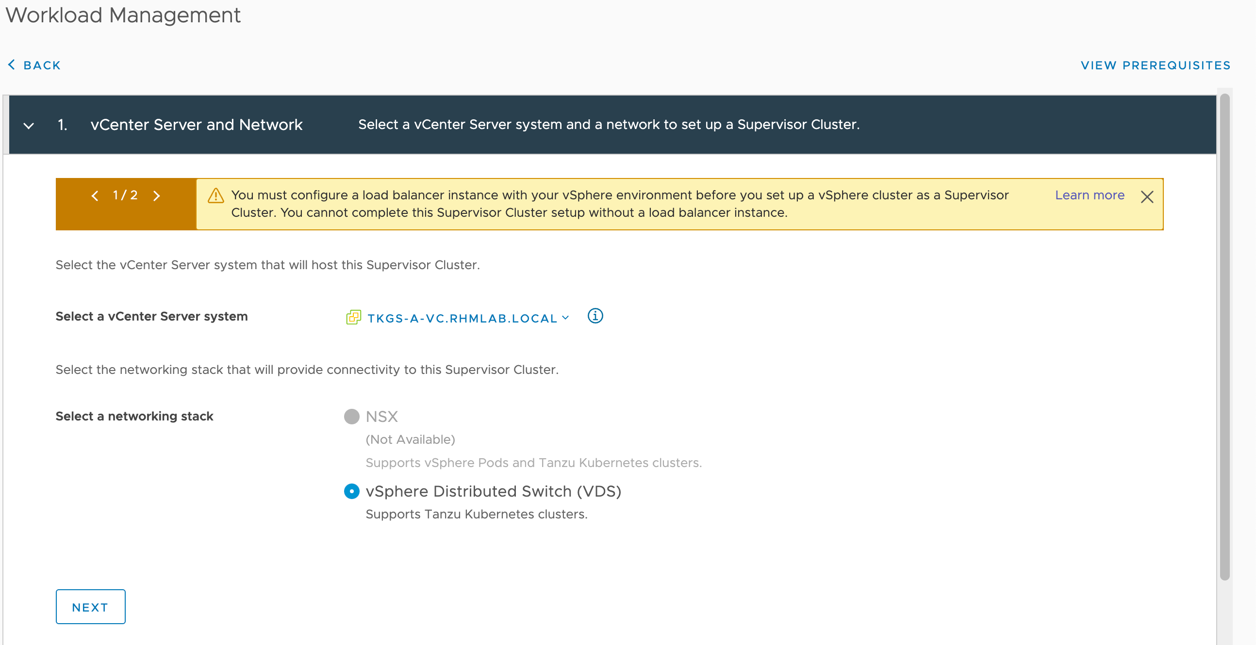
The first step in the Workload Management wizard is to select the vCenter server and the Network type. In this environment there's no NSX-T present so we're only left with VDS
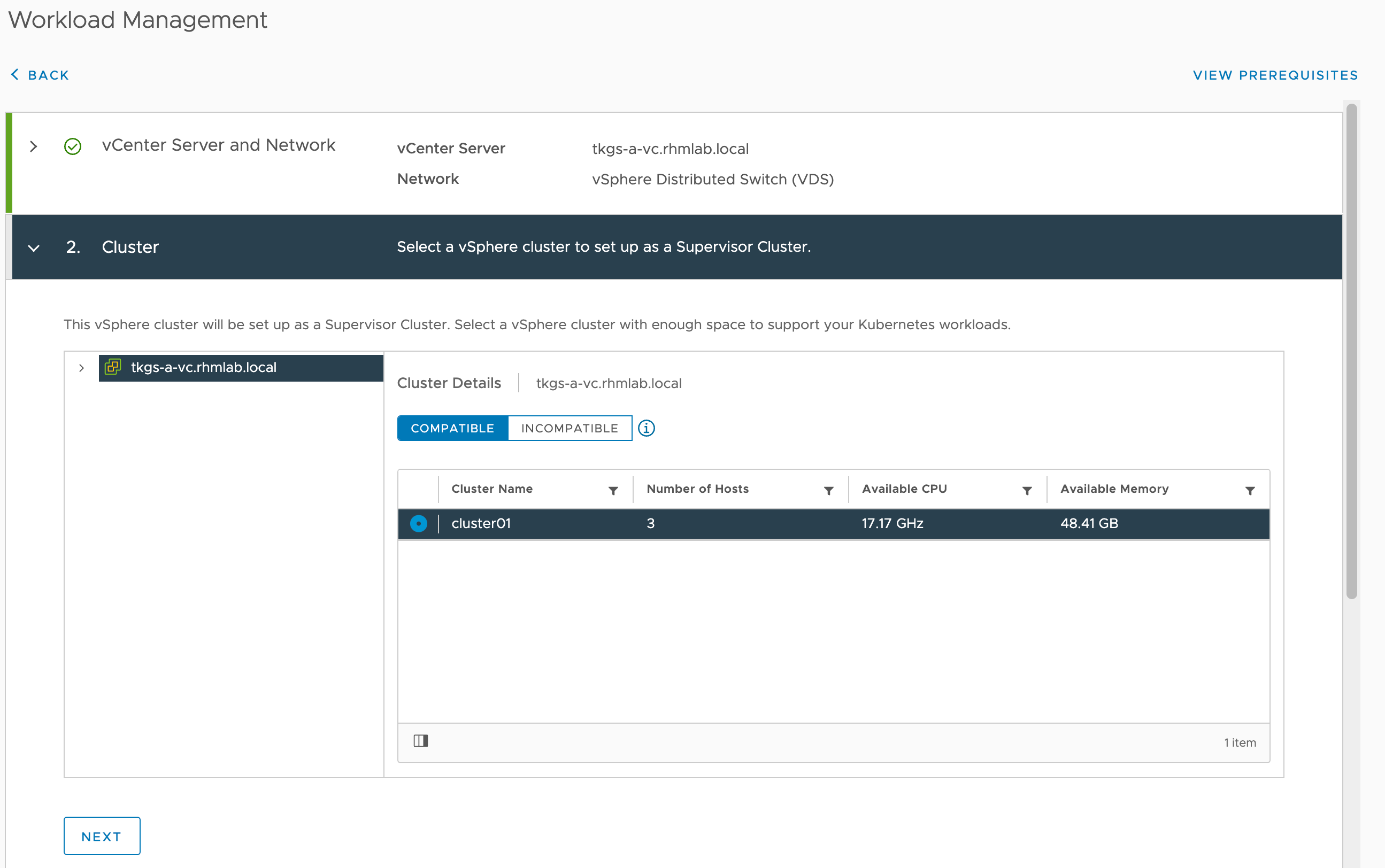
Next up is to select the cluster. The wizard will verify HA and DRS at this point so if your cluster is not listed go back and verify the prerequisites
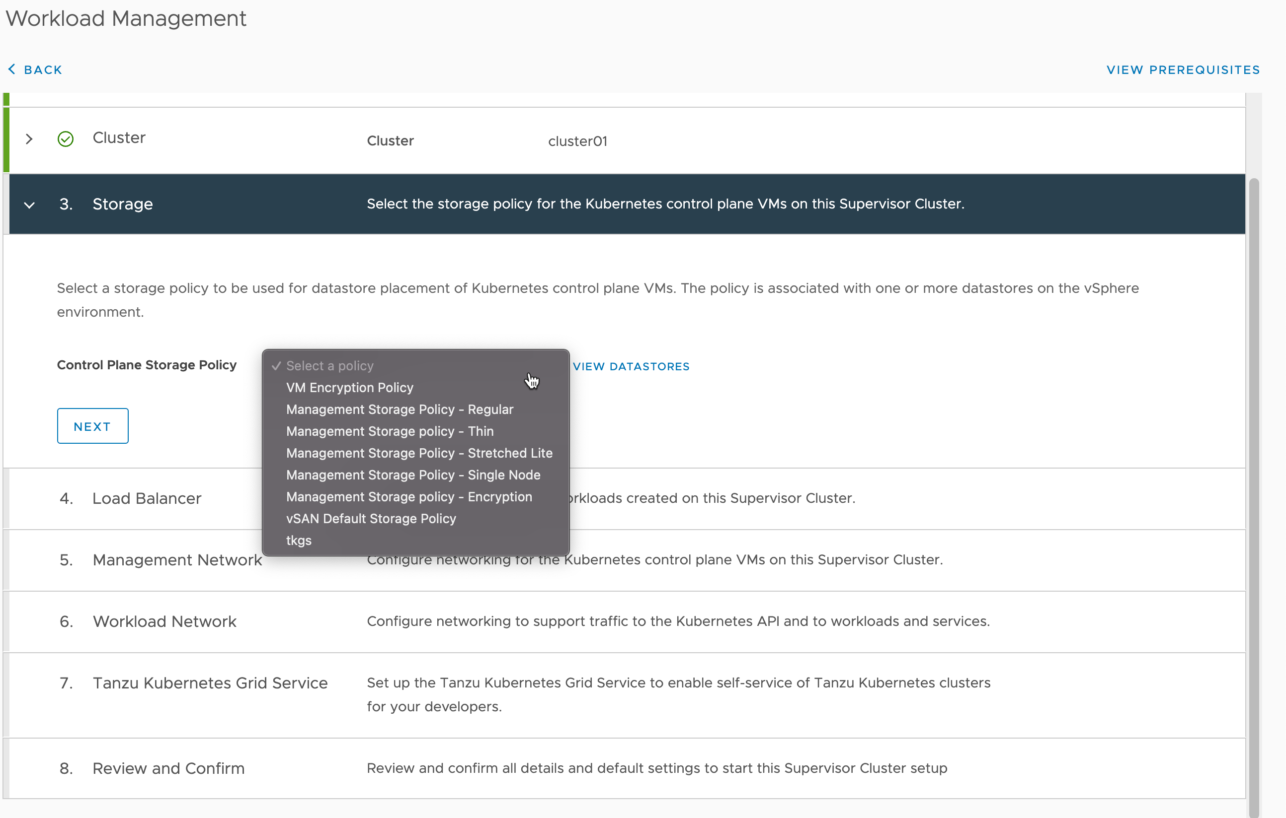
Next select the Storage policy. In this setup we'll use the bottom one, tkgs
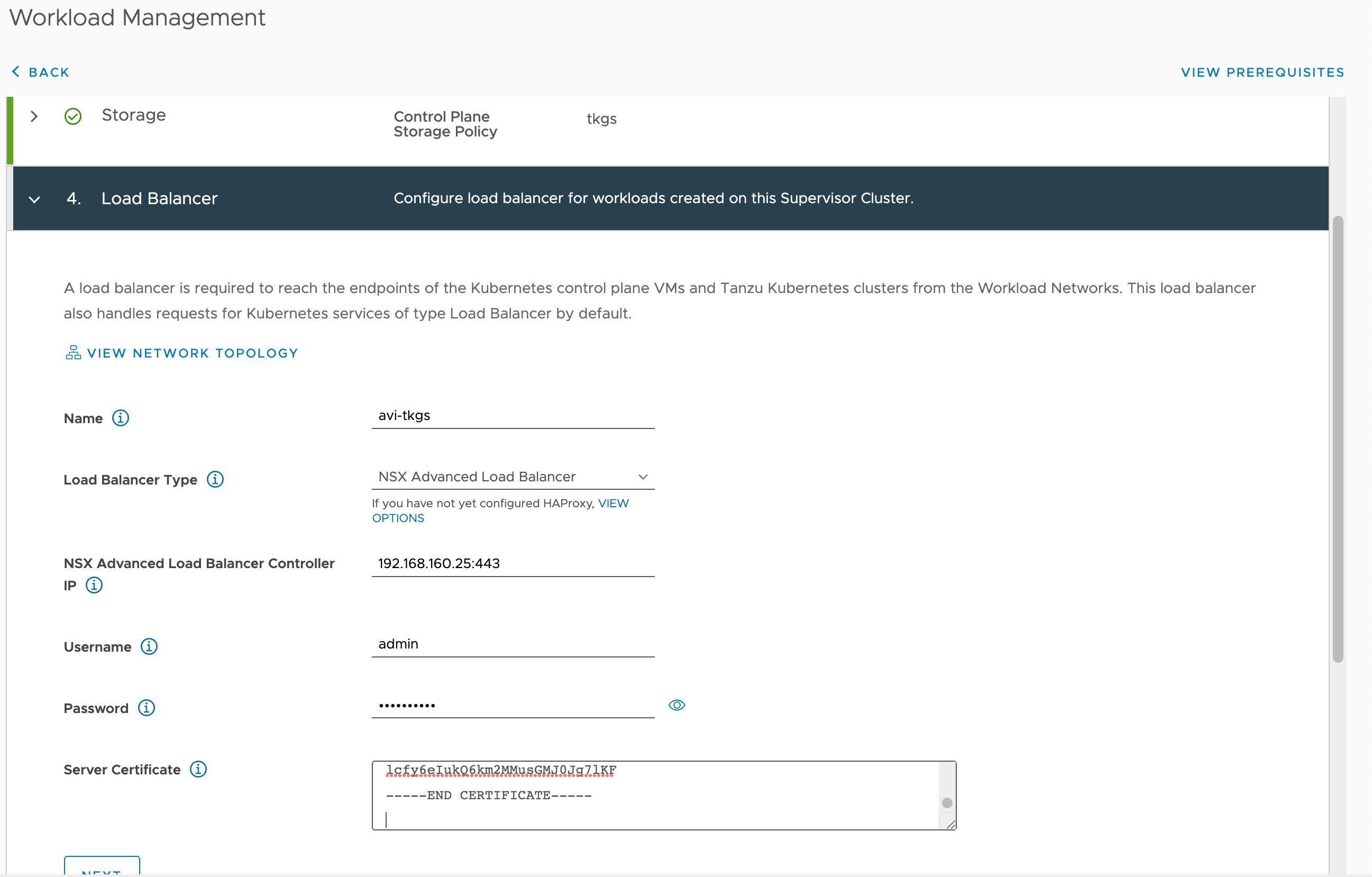
Now we'll need to enter the details about our Load Balancer which is the NSX Advanced Load Balancer. We'll enter a name for the load balancer (any DNS compliant name), the IP and port, admin credentials and provide the controller certificate
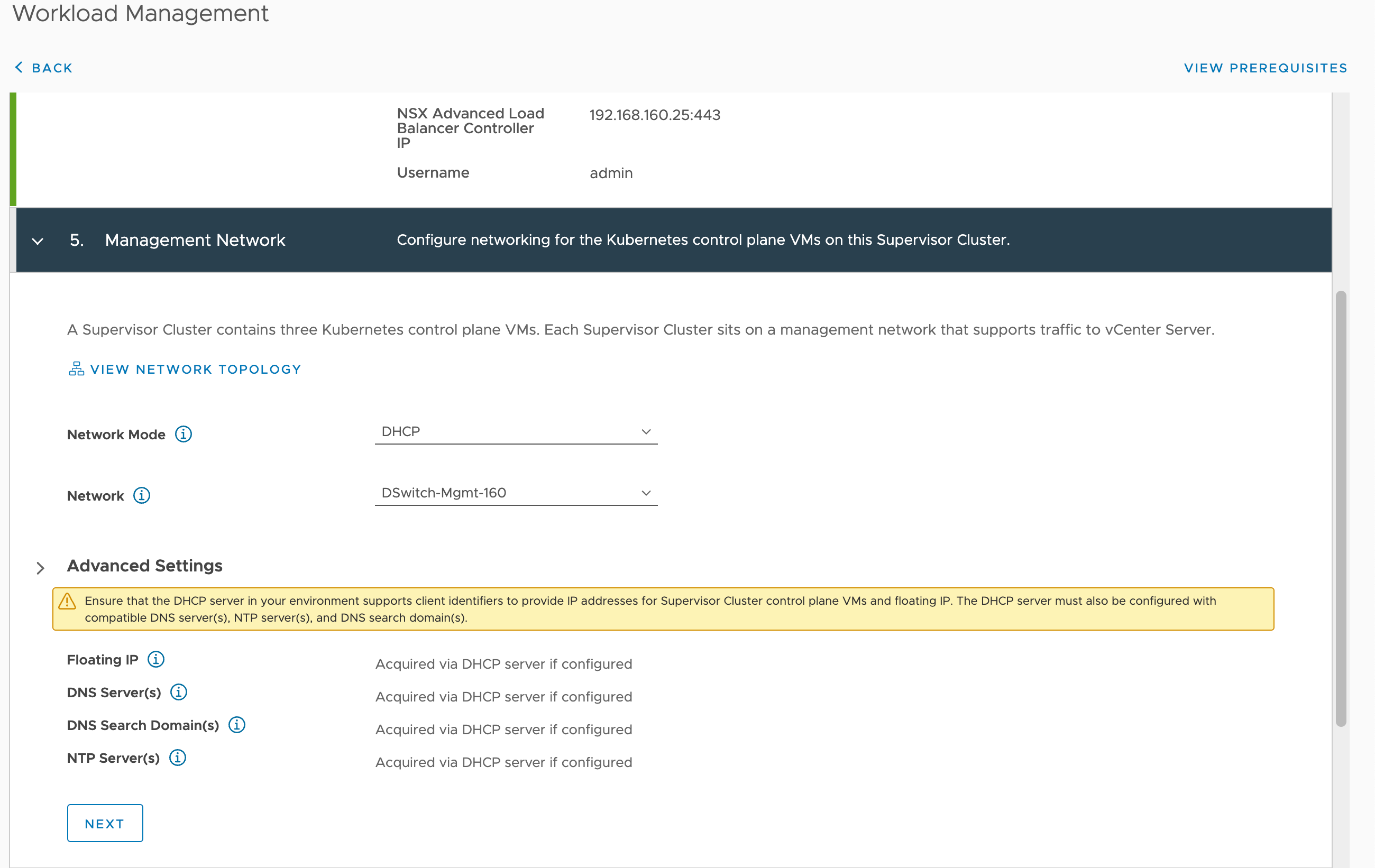
The next step is to provide the details of the Management network. The Supervisor control plane nodes needs to have a management address which supports traffic to the vCenter. We'll use DHCP in this setup making the setup quite easy and the management network selected is the same network as the vCenter is running on.
If you want/need to use static IPs make sure to provide a range of 5 consecutive IP addresses on the management network. 1 for a floating IP, 3 for the Control plane nodes, and 1 used during upgrades. Refer to the documentation for more information
Next we need to enter details for the Workload network where our workloads will run. Again we'll use DHCP for this network and select the correct Port group. Note that we can add more workload networks after the Supervisor cluster setup.
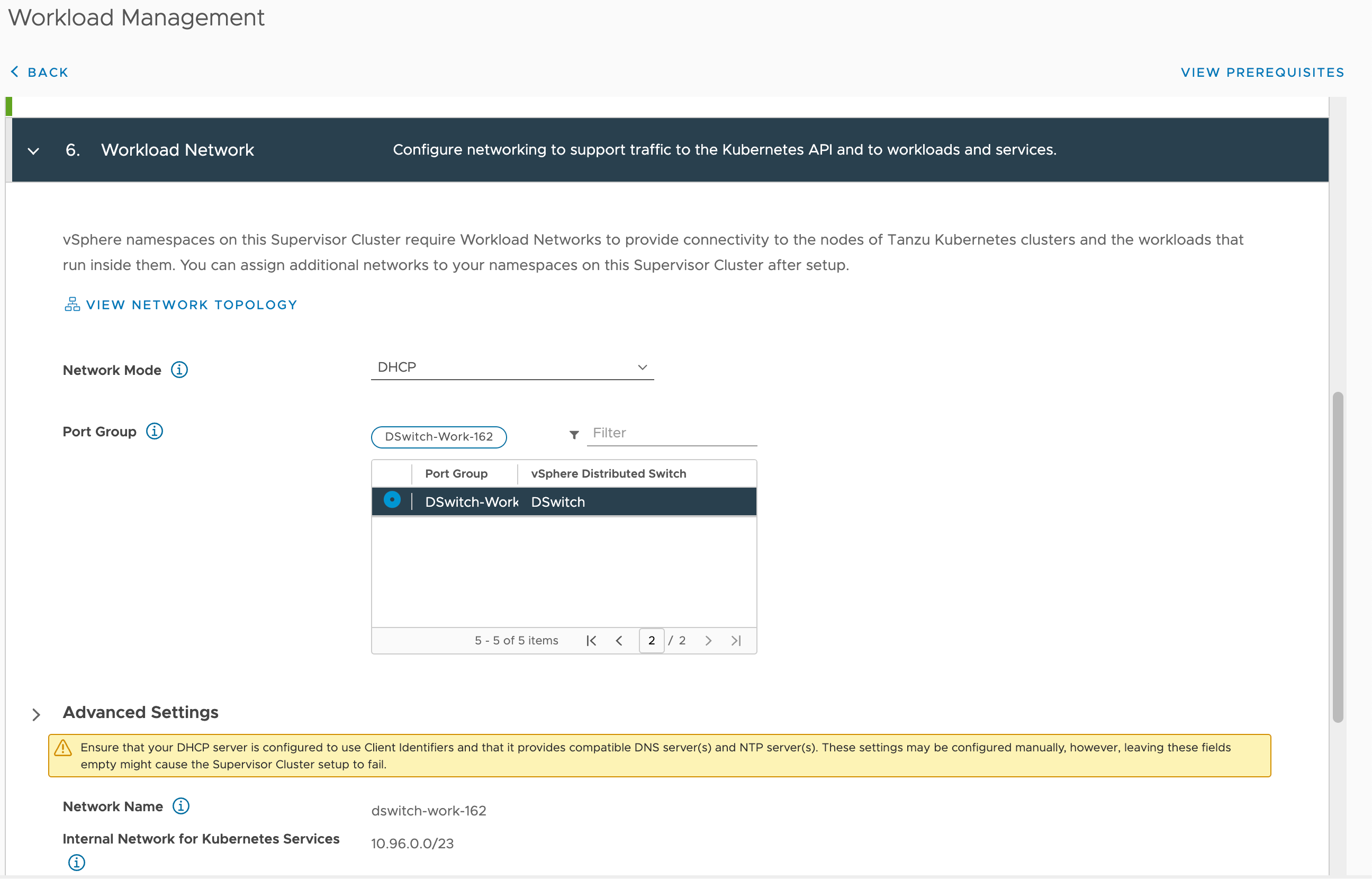
Note that DHCP and NTP is crucial services in this environment so be sure to either specify this correctly or have your DHCP server provide it, for all the networks in play.
Now we need to select the Content Library we should already have created
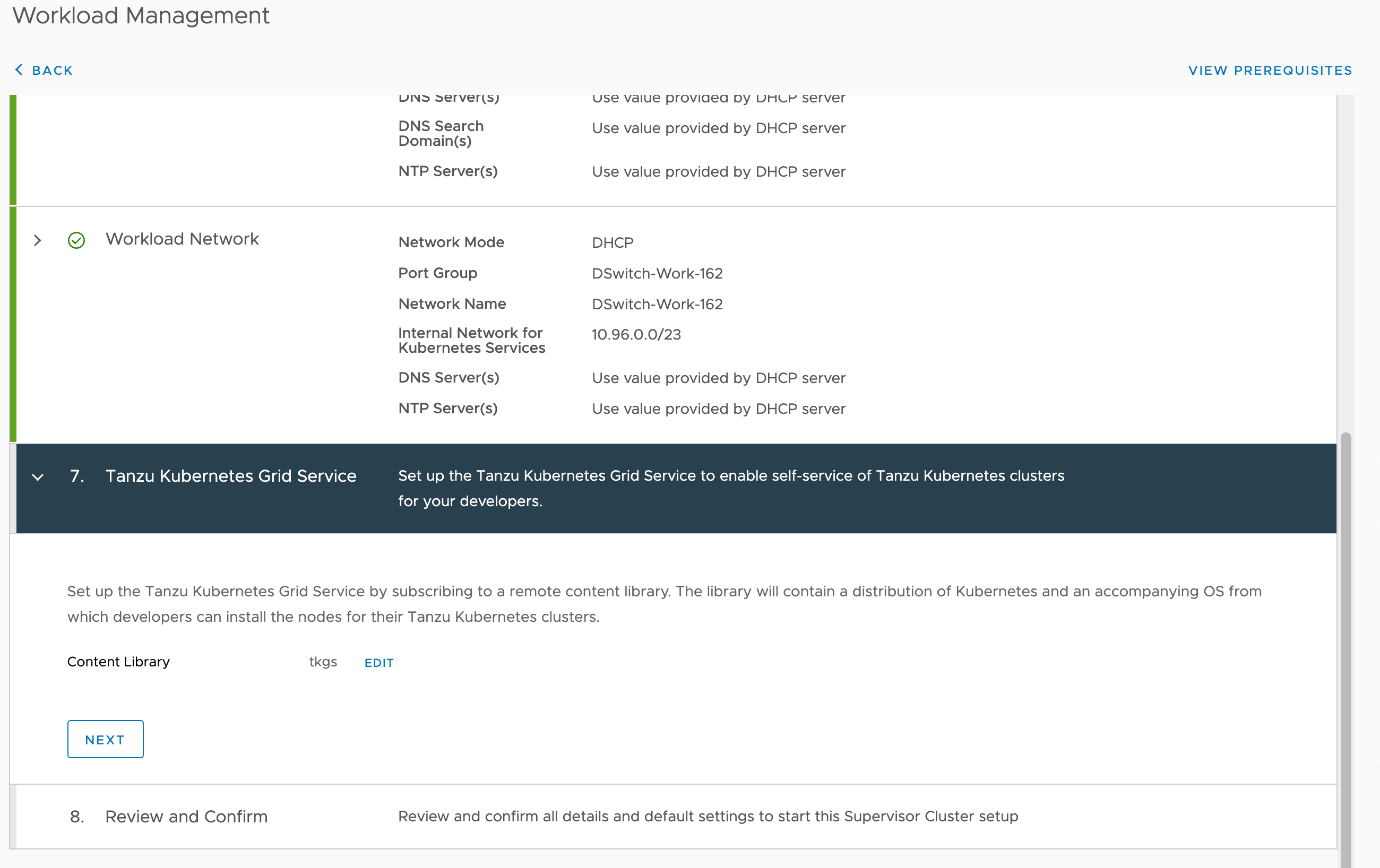
And finally we can set the size of the Control plane and optionally add in a DNS name for the API server
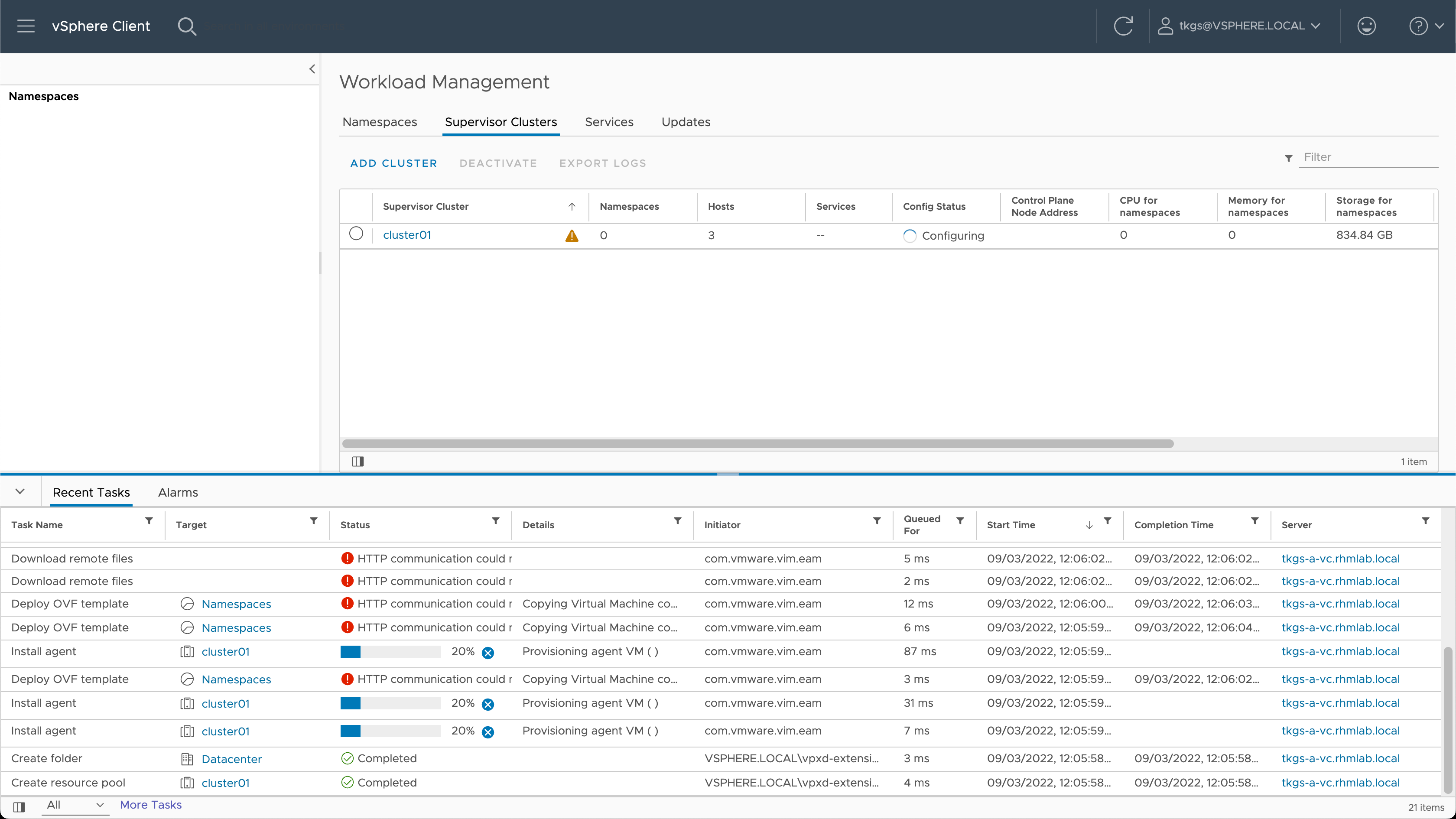
After hitting Finish in this wizard the vCenter Server will start configuring Workload Management in the cluster.
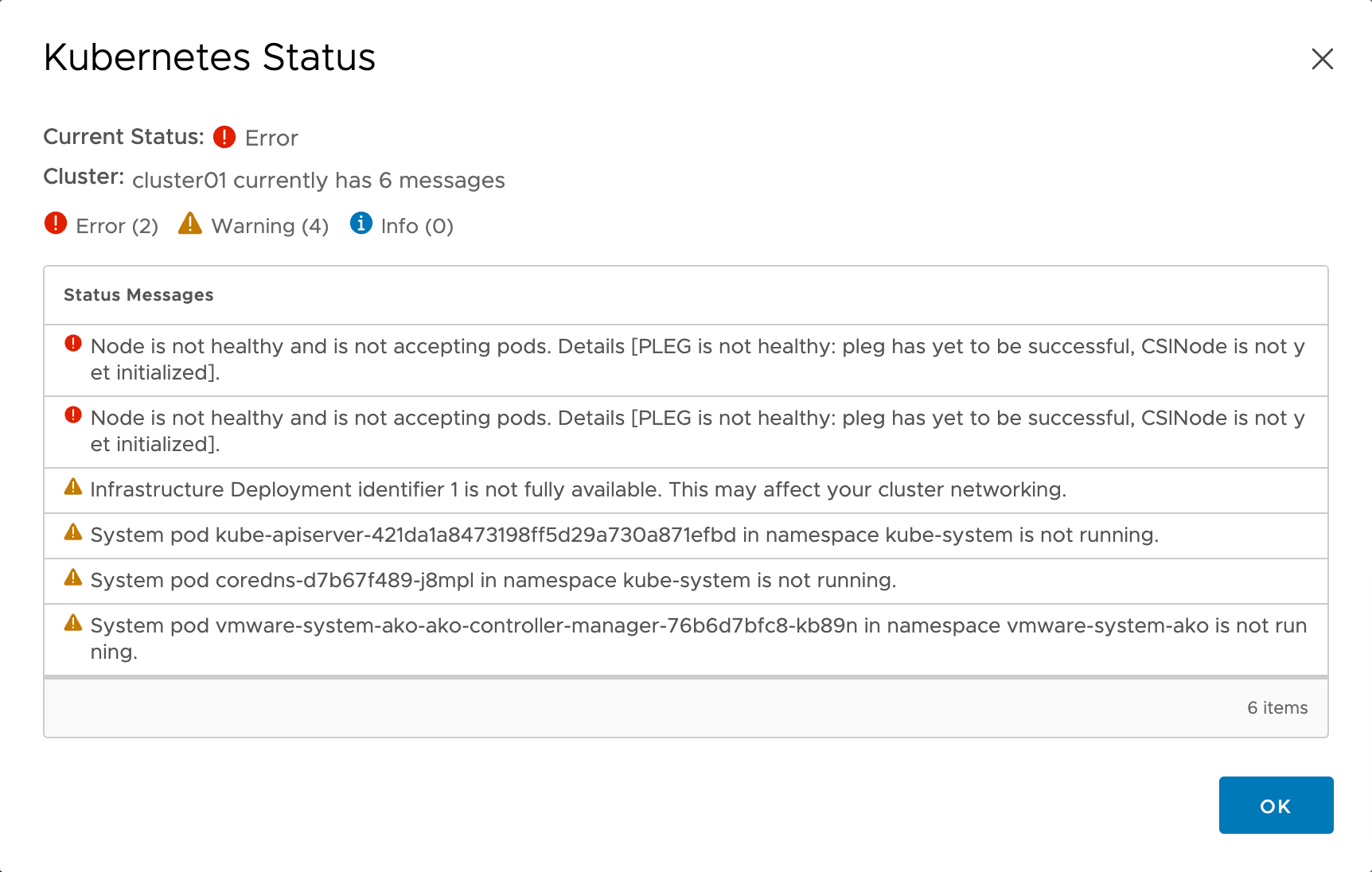
The configuration will take some time depending on the infrastructure and the selected control plane size, in my setup it takes around 25-30 minutes to deploy the Control plane nodes and do the configuration. Note that there will be quite some error messages displayed during this time so be patient
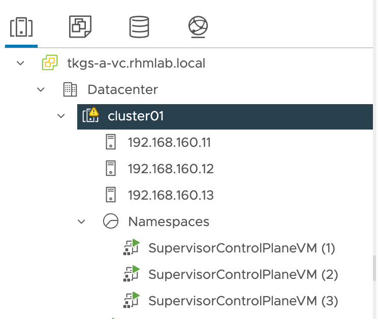
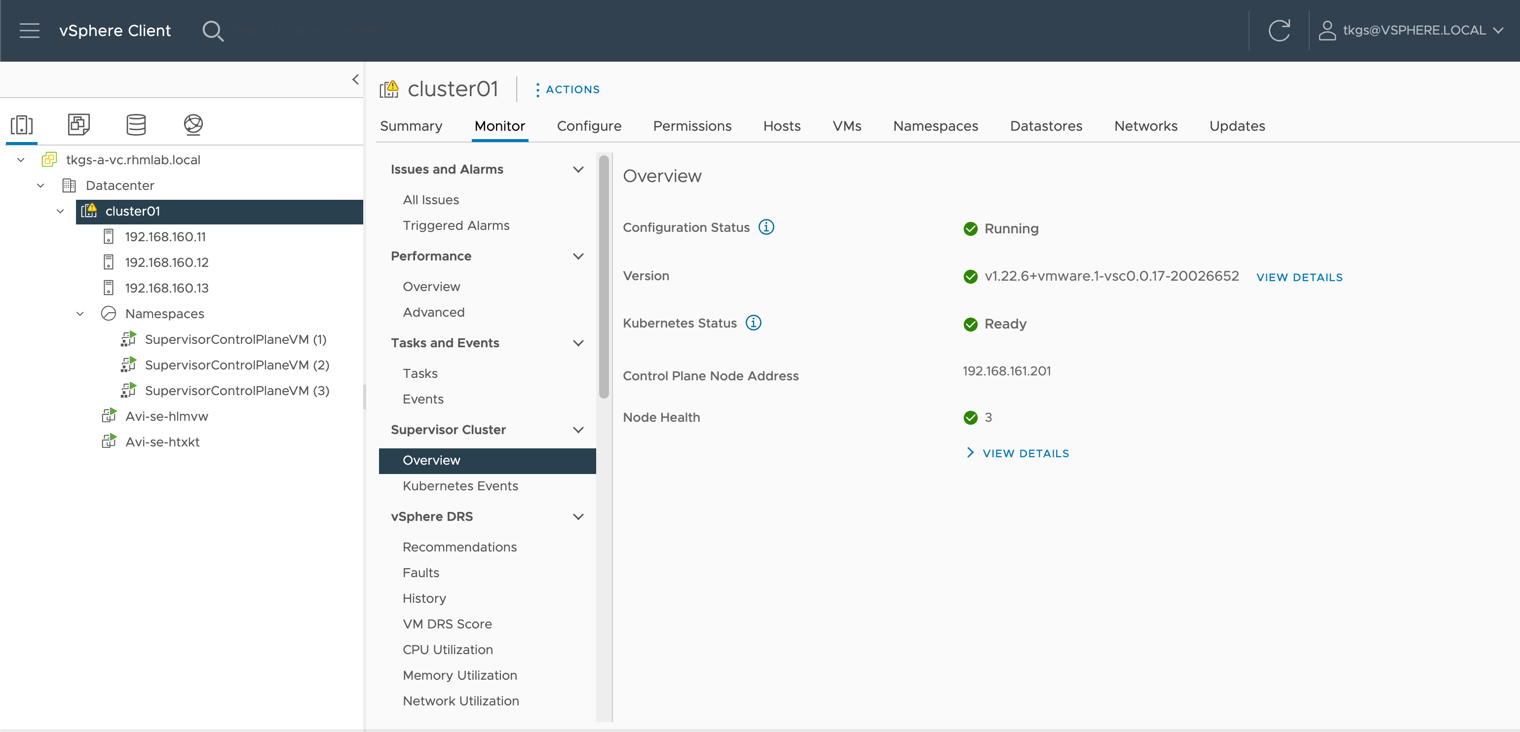
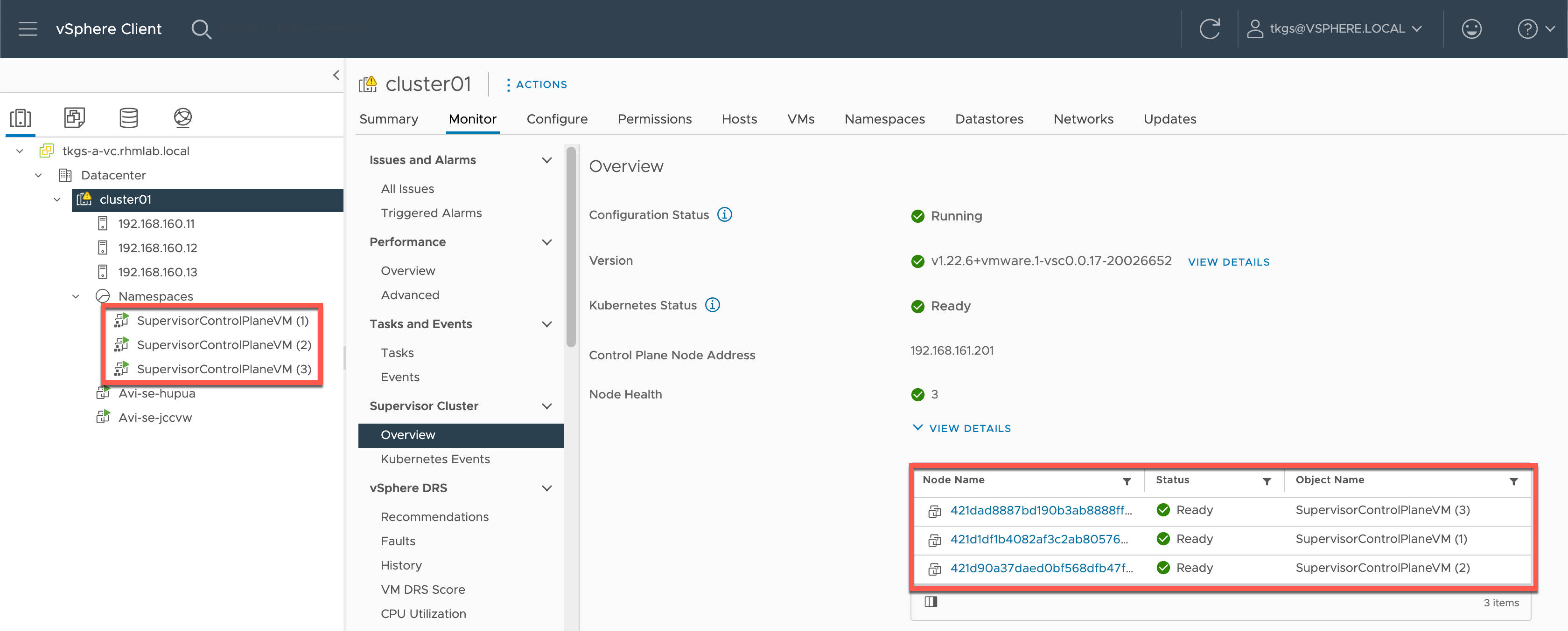
After a while the Supervisor control plane nodes should be deployed, powered on and configured
Shortly after the Control plane nodes has been boostrapped with the Kubernetes configuration needed the Workload Management enablement will use the Load Balancer API to deploy a Virtual Service for the Control plane
If no services are running on the Avi platform the first thing the controller will do is to deploy Service engines
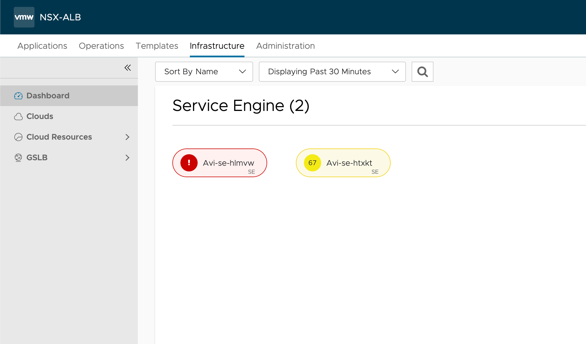
If no Service Engines have been deployed after a while there's probably something wrong with the Avi setup or with the details provided about the Load Balancer in the Workload Management wizard. Check the log messages and status messages in the UI for clues to what might be wrong.
Finally, after the Service Engines have been deployed and the Load Balancing are working, the final configuration in the Supervisor Cluster can be done by the Workload Management service and we should be up and running
Verify Supervisor cluster
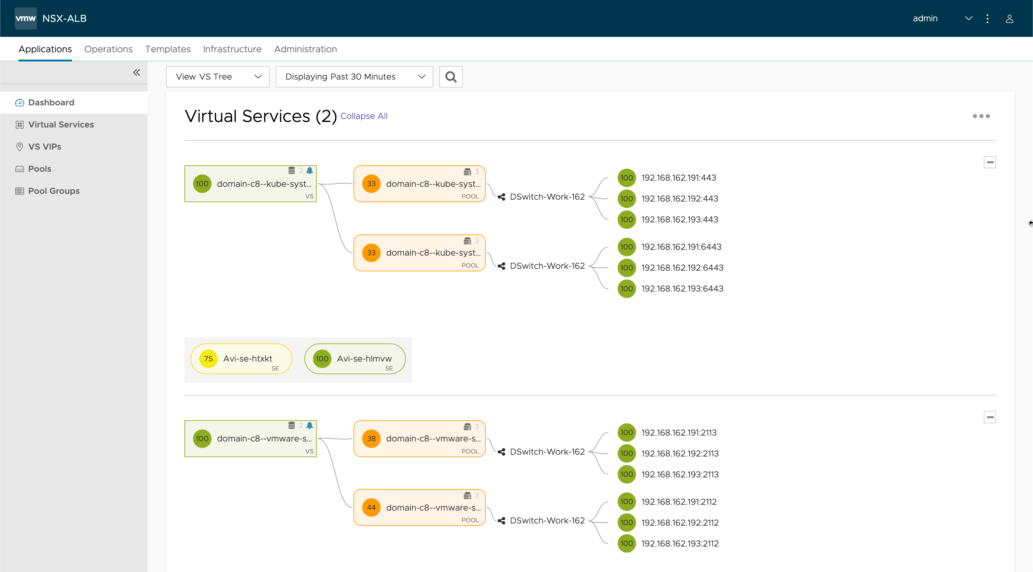
Over in the NSX Advanced Load Balancer we should now have two Virtual Services running, and we can see details about the nodes, their IP addresses and the ports in use
The two virtual services has VIPs assigned which has been pulled from the Static IP pool we've configured for the network in the Avi controller
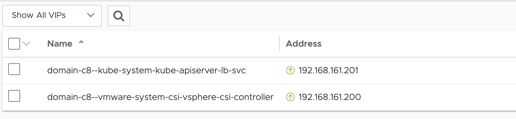
The Apiserver is what we will connect to for managing the Supervisor cluster. If we try and browse that IP we will get some instructions on how to connect to the Kubernetes control plane
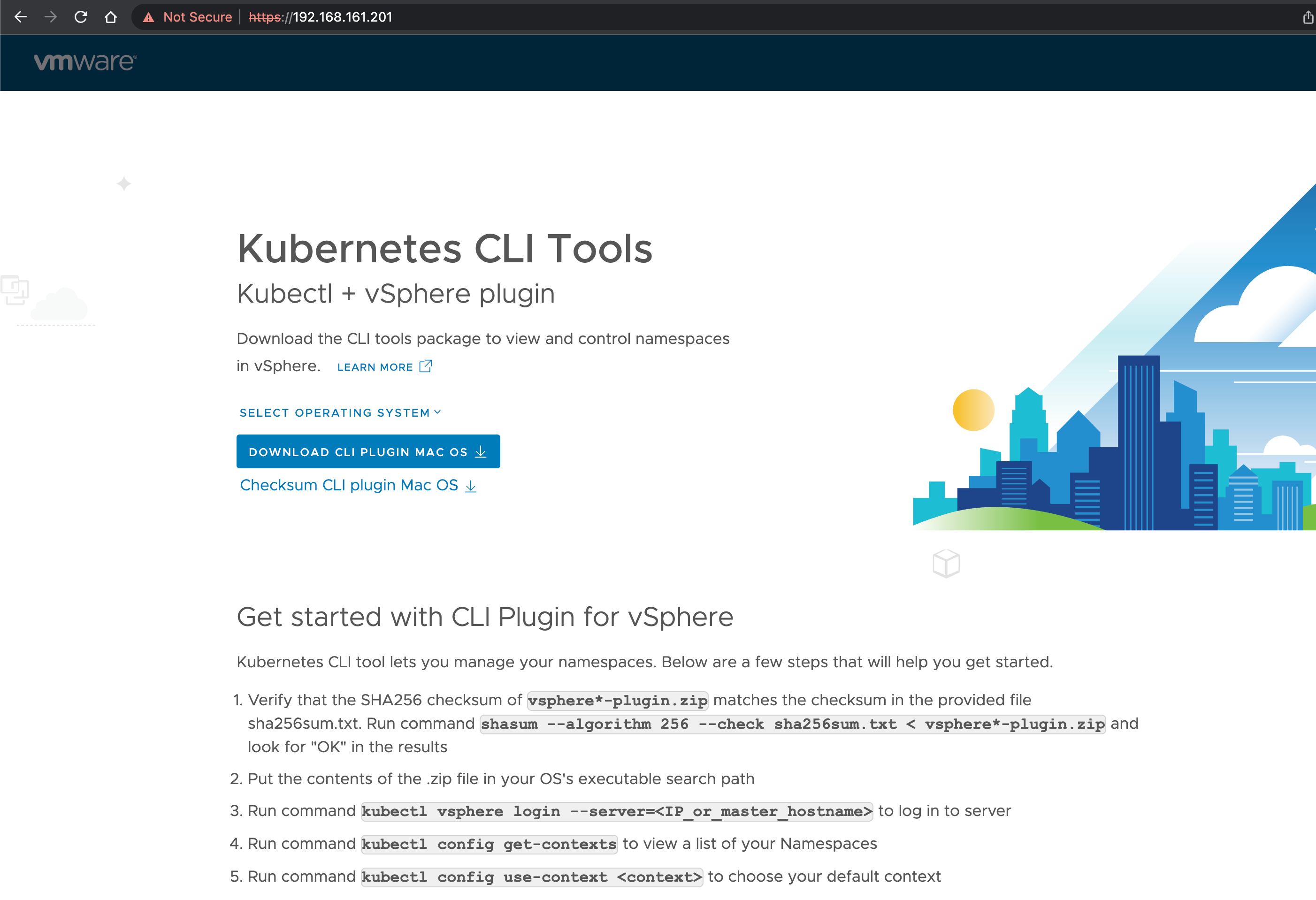
To be able to login to the Supervisor with the kubectl CLI we need to install a vSphere plugin to it. This differs based on the OS you will use so I'll refer to the documentation for instructions.
After installing the kubectl-vsphere plugin we can connect to the Supervisor cluster with kubectl
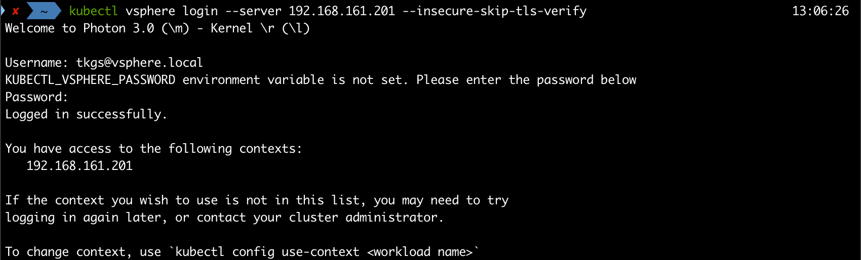
And we can list the nodes in the cluster, which should correspond to the Supervisor control plane nodes in the vSphere cluster

Summary
This concludes the initial setup of Workload Management in vSphere. In the next post we will create a namespace and deploy a Tanzu Kubernetes (guest) Cluster. Stay tuned!